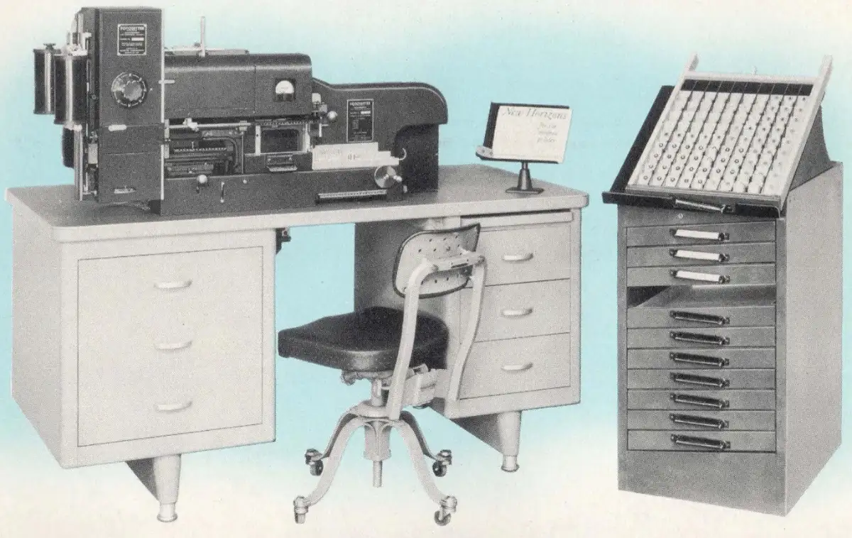
This machine was intended to produce display lines of type, such as newspaper headlines, as a Ludlow Typograph set-up would have done in a hot metal shop.
It was also suggested in the publicity material that it would also be useful for setting languages such as Chinese and Japanese, where the number of characters used was greater than the number of keys on the Intertype Fotosetter.
According to print industry historian and President of the Museum of Printing (Haverhill, Massachusetts, USA), Frank Romano: “It was for display type. Never sold. The prototype got such bad reviews that it was never officially marketed. Interesting approach however.”
The part of the machine that photographically exposed the paper was the same as on the linecaster-based Intertype Fotosetter, but the matrices were assembled by hand in a special stick, then transferred to the machine.
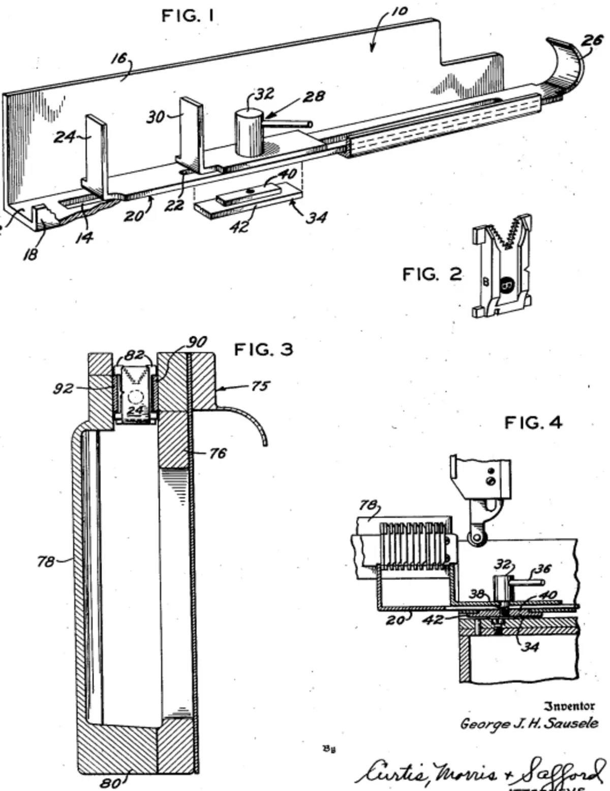
These illustrations from the US Patent Office show the stick, and the description below it is also from the patent.
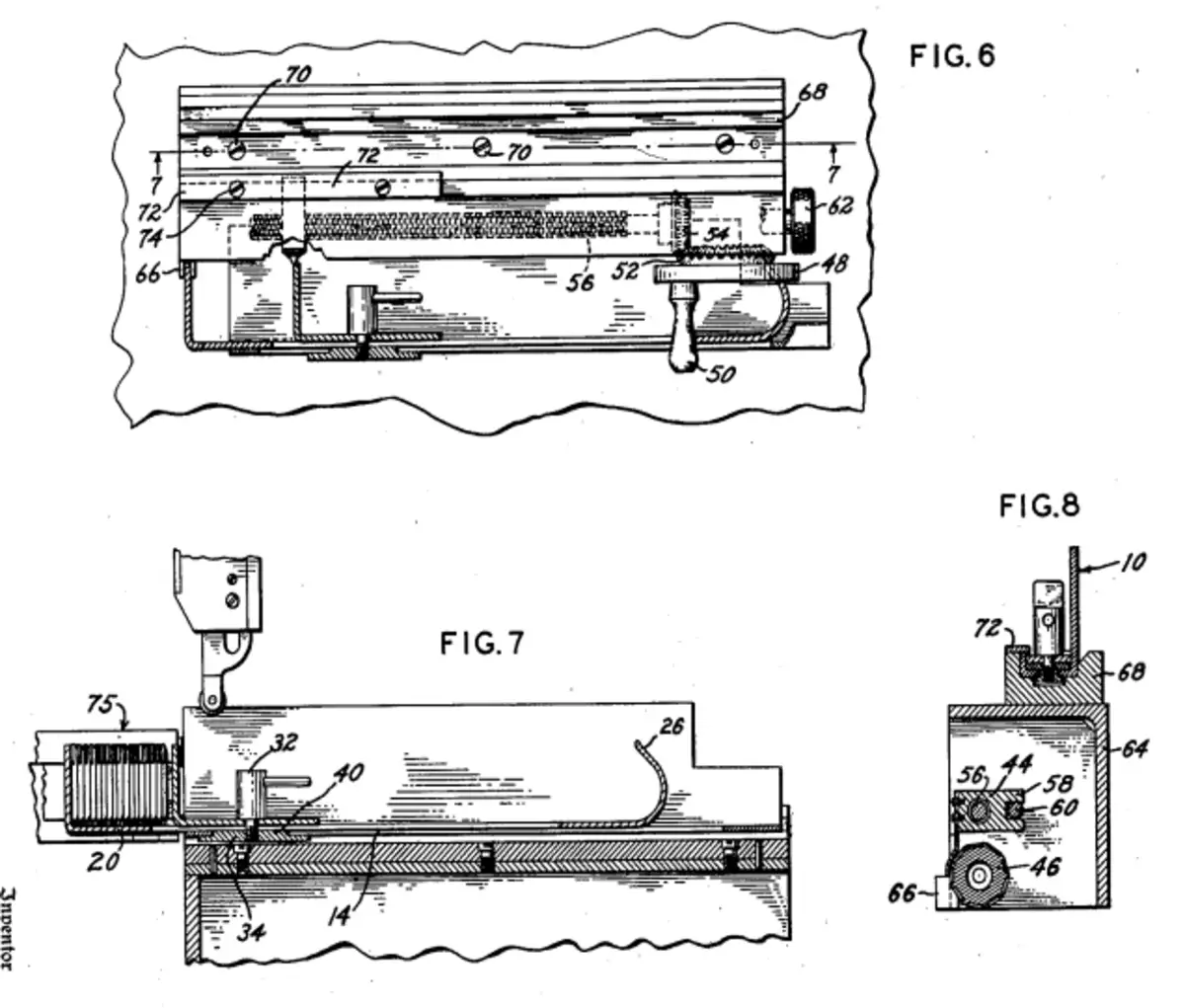
When a line of matrices has been composed in the composing device it is inserted in the machine in a manner now to be described. Referring particularly to Figs. 6, 7 and 8, secured to the top of housing 64 is a channel number 68 which is attached to the housing in any suitable manner such as by means of the screws 70.
As best shown in Fig. 8, the channel member 68 is adapted to slidably receive the slotted support 10 of the composing device which is retained in place in the channel number 68 by a plate 72 secured to the channel by the screws 74 (see Fig. 6) and overlying the channel.
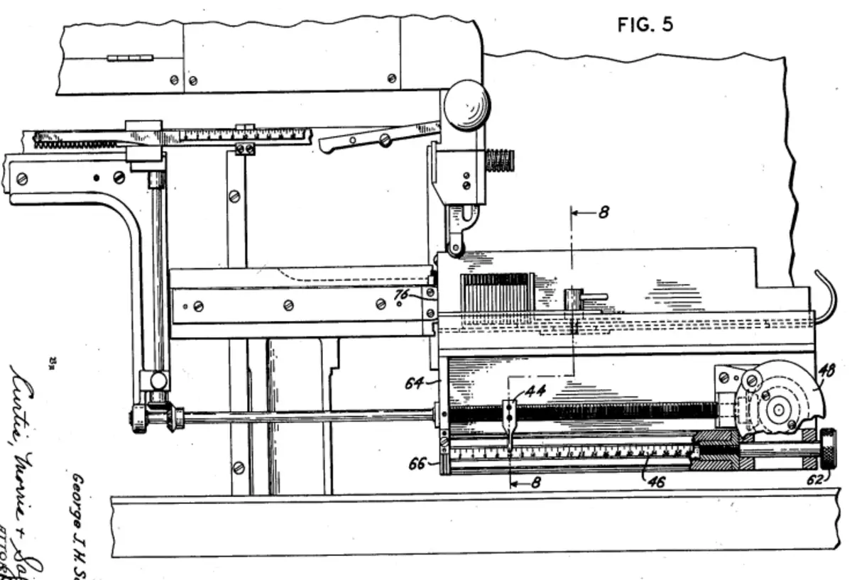
As illustrated in Fig. 5 of the drawing, the composing device slides into channel member 68 until its left-hand end strikes an abutment 76 forming part of an elevator 75 that is described below. The engaging edges of abutment 78 and slotted support 10 are aligned with the left end of housing 64.
As previously indicated, the composed line of matrices is transferred from the composing device to a justifying station by apparatus that includes the elevator 75, the construction of which is best shown in Fig. 3.
Referring to this figure the elevator 75 is of U-shaped cross-section and comprises a front arm 76, rear arm 78 and inter-connecting block 80. Referring to Fig. 7, the composed line of matrices is inserted into elevator 75 by manually grasping the curved end 26 of assembler slide 20 and urging the left-hand end of the assembler slide between the upper ends of arms 76 and 78 until the upper step 49 of shoe 34 engages the end of slot 14. The slot 14 is of such length that when it is engaged by the step 40 the composed line will be properly positioned within the elevator.
Reverting to Fig. 3, the matrices are provided with upper ears 82 and lower ears 84 that extend laterally beyond the sides of the assembler slide 20. The arms 76 and 78 of elevator 75 are provided with the shelves 90 and 92 respectively positioned to engage the upper ears 82 of the matrices of the line. Thus as the elevator 75 is lifted, the line of matrices is moved thereby from the assembler slide 20. This removal of the line of matrices from the assembler slide is particularly shown in Fig. 4.
Are you interested in Early Photosetting machines? Check out the Early Photosetting Chat section of the Metal Type Forum.